Data Elements
Hello and welcome to another blog post here at SkyNet-SH. In this post I will be taking you through the data elements, providing an explanation and illustrative diagram for each. The topics I will be covering are; Cyclic Redundancy Check (CRC), Encapsulation, Datagrams, Address and Sequencing.
Cyclic Redundancy Check (CRC)
Cyclic Redundancy Check which is often abbreviated to CRC is a technique that works with and alongside error detection and error correction. CRC is active whilst data is being transmitted across devices and is in place to detect errors and hopefully resolve them, which is in the form of error correction. CRC is used throughout wired LAN connections and this is a technique which is implemented via a polynomial; this is a series of formulae that involve the same number.
The process of CRC is that it will divide the data by a number and then produce a result and the answer will usually be very precise meaning it will not just be a simple integer, instead it will most likely be a decimal which means there will be a remainder. This remainder will then be repackaged in with the original data and be re-calculated in the receiver device. Once the receiver devices receives the data along with the remainder, it will test the value to see if it is correct, if it isn't the outcome will resolve in an error being detected and this usually means that there must of been some form of data corruption during transmission. Therefore, data correction is executed and attempts to resolve and re-calculate the data.
Encapsulation (Frames and Packets):
Encapsulation is a process that deals with large files which are being sent across a wired network; WAN or LAN, it will split the file into smaller individual parts to make it easier and quicker for data transmission. In encapsulation, a frame is the actual data which is being sent between two devices and a series of these are known as packets. Each packet includes the main data which is known as a payload and is a 'term used to describe the data being sent.' (BTEC Level 3 - K. Anderson, 2010)
Datagrams:
Datagrams are considered to be a less reliable counterpart in regards to packets, but both are seen to be sent in a similar manor. The main difference is packets are sent via TCP and IP, which ensures that the data being transferred arrives at its destination. Compared to a datagram which is sent via UDP and IP, which ensures that it is sent as high quality as possible, regardless of whether it reaches its destination successfully or not.
Address:
Addresses are an important variable throughout networking and they are essential for providing a valid file path for data which is being transferred. There are two types of address; physical address and logical address, a physical address can be coded onto a network device and an example of this would be a MAC address, which identifies network communication interfaces that have been assigned to it. MAC addresses are commonly associated with Ethernet and WI-FI connections; wired and wireless. The second type of network is known as a logical address that can be set-up by a network administrator or network server, and an example of this would be an IP (Internet Protocol) address, which is a unique string of numbers that act as an identity for the device on the Internet.
Sequencing
When a file is being transmitted to another device across the network, they are split into packets and datagrams and to ensure that they are reassembled correctly and in order, they are given a unique identification number which is known as a 'sequence number'. If this number wasn't assigned to each packet and/or datagram, files would become out of sync and the data would not make sense, resulting in an error.
SkyNet-SH
Thank you for reading through today's post. I hope you have found something useful and worth knowing. Please stay tuned for more information, here at SkyNet-SH
Reference:
Base Information - Anderson, K. Jarvis, A. Kaye, A. Lawson, J. McGill, R. Phillips, J. and Smith, A. . Information Technology Level 3 Book 1 BTEC National. Harlow: Pearson Education Limited.
Friday, 30 January 2015
Monday, 26 January 2015
Communication Models and Protocols - SkyNet-SH
Once again, it's a hello from me and welcome to yet another post here at SkyNet-SH. In this entry I will be talking about communication models and protocols, such as; Open System Interconnect, TCP/IP, WI-FI, Bluetooth, 3G and 4G and wireless security protocols (WEP, WPA).
Firstly, we will begin with communication models...
Open System Interconnection - OSI
TCP/IP
Firstly, we will begin with communication models...
Open System Interconnection - OSI
Open System Interconnection or OSI is an ISO standard for worldwide communication that defines a networking framework, this implements protocols onto seven layers; Application, Presentation, Session, Transport, Network, Data Link and Physical. Control is passed between one layer to the next, starting at the Application layer and ending at the Physical layer.
 |
| Figure 1. OSI Model - Layers (Datacombasic.blogspot.co.uk, 2011) |
In this image (see Figure 1.), it shows the seven layers which make up the OSI model, it also shows the layer description and the data type. This diagram is quite detailed, informative and generally helps explain this model.
Functions of OSI Layers
In this next section I will be explaining the functions of the OSI model, going through each layer...
Layer 1 - Physical
Layer 1 - Physical transmits data in sequences of bits, which include; electrical impulse, light or radio signal. It also provides the hardware capability of sending and receiving data on a carrier; including set cables, cards and physical aspects. Fast Ethernet and ATM are protocols with Physical layer properties.
Layer 2 - Data Link
Layer 2 - Data Link covers the encoding and decoding processes of data packets. It then looks at transmission protocols and also management, while going back to Layer 1, in order to resolve errors, flow control and frame synchronisation. This layer is split up into two smaller layers; MAC, which stands for Media Access Control and LLC, which stands for Logical Link Control.
The job of the MAC layer is to control how a computer on the network accesses data and gains the permission to transmit it, while the job of the LLC layer is to control frame synchronisation, flow control and error checking.
Layer 3 - Network
Layer 3 - Network provides the network with the technologies for switching and routing. It can create paths known as virtual circuits which are used for transmitting data between nodes. Other functions related to this layer are routing and forwarding, addressing, inter-networking, error-handling, congestion-control and packet sequencing.
Layer 3 - Network provides the network with the technologies for switching and routing. It can create paths known as virtual circuits which are used for transmitting data between nodes. Other functions related to this layer are routing and forwarding, addressing, inter-networking, error-handling, congestion-control and packet sequencing.
Examples of Network are AppleTalk and IP (Internet Protocol).
Layer 4 - Transport
Layer 4 - Transport provides clear transfer of data between systems and devices and also has the job of delivering error-free messages in order without any data loss.
Layer 4 - Transport provides clear transfer of data between systems and devices and also has the job of delivering error-free messages in order without any data loss.
The Functions of the Transport layer are:
- The layer will accept a message from the next layer (Session), while splitting the message into smaller units and then passing them onto the Network layer. The next step would be for the layer to reassemble the message.
- When there aren't any message buffers available, the data transmitting station will stop sending messages.
Layer 5 - Session
Layer 5 - Session allows session establishment between processes running on different stations. It provides applications on different machines to establish, use and end a connection, which is called a session. Session support performs the functions that allow these processes to communicate over the network, performing security, name recognition, logging and so on.
Layer 5 - Session allows session establishment between processes running on different stations. It provides applications on different machines to establish, use and end a connection, which is called a session. Session support performs the functions that allow these processes to communicate over the network, performing security, name recognition, logging and so on.
Layer 6 - Presentation
Layer 6 - Presentation sets the data to be presented to the application layer. It can be viewed as the translator for the network. This layer may translate data from a format used by the application layer into a common format at the sending station, then translate the common format to a format known to the application layer at the receiving station.
This layer provides the following functions:
- Character code translation
- Data conversion: bit order
- Data compression: reduces the number of bits that need to be transmitted over the network.
- Data encryption: encrypt data for security purposes, for example; ASCII, TIFF, GIF, JPEG, MPEG
Layer 7 - Application
Layer 7 - Application serves as the window for users and application processes to access network services. This layer contains a variety of commonly needed functions:
- Resource sharing and device redirection
- Remote file access
- Remote Printer access
- Inter-process communication
- Network management
- Directory services
- Electronic messaging; e-mail and SMS
- Network Virtual Terminals
Transmission Control Protocol/Internet Protocol or TCP/IP is a communication protocol that connects hosts to the Internet and it is used for transmitting data across a network. The TCP/IP model has four layers; Application, Transport, Internet and Network Interface.
In the image to the left (see Figure 2.), it shows the TCP/IP model with its four layers; Application, Transport, Internet and Network Interface.
The Internet is also based on this model and includes lots of protocols which have various different uses.
The protocols that this model works with are; HTTP, HTTPS, FTP, POP3, SMTP, DNS, TCP and IP. Other protocols also exist.
Layer 1 - Network Interface
Layer 1 - Network Interface revolves around user interaction and presentation of data. It is also responsible for implementing packets on the network and also receiving them. TCP/IP was developed to be independent on the network and because of this it is used to connect to different network types. The network types are mostly LAN networks, such as; Ethernet, WAN and Token passing.
Layer 2 - Internet
Layer 2 - Internet, organises moving data on a network and it is also responsible for various different functions, the main protocol of this layer is IP (Internet Protocol), and on its own, allows the user to address a package and place into the system, however, there isn't a direct link between the user and the recipient. However, when the IP protocol is part of TCP/IP is allows a connection between the two people meaning they can send data back and forth for a period of time.
Layer 3 - Transport
Layer 3 - Transport is responsible for providing the Application layer with session and datagram communication services. The main protocols of this layer are TCP and UDP (User Datagram Protocol).
Layer 4 - Application
Layer 4 - Application provides applications the ability to access services from other layers and then defines the protocols that the applications use to exchange data. Although there are already many Application layer protocols, more are always being developed.
 |
| Figure 2. TCP/IP Four Layer Model (SHawes, 2015) |
In the image to the left (see Figure 2.), it shows the TCP/IP model with its four layers; Application, Transport, Internet and Network Interface.
The Internet is also based on this model and includes lots of protocols which have various different uses.
The protocols that this model works with are; HTTP, HTTPS, FTP, POP3, SMTP, DNS, TCP and IP. Other protocols also exist.
Layer 1 - Network Interface
Layer 1 - Network Interface revolves around user interaction and presentation of data. It is also responsible for implementing packets on the network and also receiving them. TCP/IP was developed to be independent on the network and because of this it is used to connect to different network types. The network types are mostly LAN networks, such as; Ethernet, WAN and Token passing.
Layer 2 - Internet
Layer 2 - Internet, organises moving data on a network and it is also responsible for various different functions, the main protocol of this layer is IP (Internet Protocol), and on its own, allows the user to address a package and place into the system, however, there isn't a direct link between the user and the recipient. However, when the IP protocol is part of TCP/IP is allows a connection between the two people meaning they can send data back and forth for a period of time.
Layer 3 - Transport
Layer 3 - Transport is responsible for providing the Application layer with session and datagram communication services. The main protocols of this layer are TCP and UDP (User Datagram Protocol).
Layer 4 - Application
Layer 4 - Application provides applications the ability to access services from other layers and then defines the protocols that the applications use to exchange data. Although there are already many Application layer protocols, more are always being developed.
Thursday, 22 January 2015
Access Methods - SkyNet-SH
Welcome everyone to another Blog post here at SkyNet-SH. Today I will be bringing you information regarding access methods, including information about CSMA/CD, CSMA/CA and also token passing.
CSMA/CD - Carrier Sense Multiple Access with Collision Detection
CSMA/CD or Carrier Sense Multiple Access/Collision Detection is a set of rules or protocols that determine how network devices respond when two devices or system attempt to use the same data channel at the same time, resulting in a collision. Ethernet cables used CSMA/CD to monitor the incoming and outgoing data. If there are no other transmissions at the same time as one then it will be able to complete the transmission successfully. However, if there are two attempts which occur at the same time, then this will result in a collision. The main job of the CSMA/CD is to detect any collisions in the data channel and then resend the data.
CSMA/CA - Carrier Sense Multiple Access/Collision Avoidance

CSMA/CD - Carrier Sense Multiple Access with Collision Detection
CSMA/CD or Carrier Sense Multiple Access/Collision Detection is a set of rules or protocols that determine how network devices respond when two devices or system attempt to use the same data channel at the same time, resulting in a collision. Ethernet cables used CSMA/CD to monitor the incoming and outgoing data. If there are no other transmissions at the same time as one then it will be able to complete the transmission successfully. However, if there are two attempts which occur at the same time, then this will result in a collision. The main job of the CSMA/CD is to detect any collisions in the data channel and then resend the data.
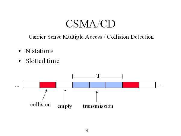 |
| Figure 1. CSMA/CD Process (Courses.cs.washington.edu, 2015) |
In this image (see Figure 1.), it shows how CSMA/CD works and in the data channel, where the collision can occur.
CSMA/CA or Carrier Sense Multiple Access/Collision Avoidance is a network protocol that looks at the network in order to sense and avoid a collision. The difference between CSMA/CA and CSMA/CD is that CD detects the collision but only deals with it once the collision has been confronted, while CA tries to avoid the collision before contact.
Once CSMA/CA has detected the collision it tells the other connected devices not to broadcast data until the collision has been completely avoided.
In the flowchart above (see Figure 2.) it shows the process of how CSMA/CA (collision avoidance) works.
Once CSMA/CA has detected the collision it tells the other connected devices not to broadcast data until the collision has been completely avoided.
 |
| Figure 2. CSMA/CA Flowchart Diagram (Networking-forum.com, 2015) |
Token Passing
In CSMA/CD and CSMA/CA there is always a possibility that a collision could occur. As the number of hosts in the network increase the possibility of collisions will also increase. In token passing, when a host wants to transmit data it should be able to hold the token, which is an empty packet. The token is circling the network at high-speed and if any nodes are wanting to transmit data, it should then wait for the token. When the token has reached the node, the node is then able to take the token from the network, fill it with data, mark the token as being used and then place it back into the network.
Token passing is often associated with circling around the ring topology network. As pictured below (see Figure 3.).
SkyNet-SH
As always thank you for reading today's post, I hope you have managed to learn about some of the access methods that have been basically explained in this post. Next time I will be talking about 'communication models and protocols', so stay updated for that...Wednesday, 21 January 2015
Network Services - SkyNet-SH
Hello and welcome to another post, here at SkyNet-SH.
Today I will be introducing you to network services, explaining what services are available and how they have developed over their timelines.
The limitations are that ISDN can be very costly because it requires specialised digital devices. This network service would be used for connections in remote sites, or for customers such as a small business or home users. Additionally, a limitation is that the resources you send outside to the other networks will not be permanently available to other internet users; this is because ISDN functions in a way where you send video, voice, and data that cannot be retrievable afterwards.
ADSL Broadband:
ADSL Broadband, (Asymmetric Digital Subscriber Line) has high speed for data transmission in which a single line or cable is capable of carrying large amounts of data at once. The most common form of broadband connections is cabled modems which provide a continuous connection to homes and businesses.
The benefits of broadband are that it is considerably faster than its predecessor baseband with technological advancements. Furthermore, another benefit is that it is easy to set up nowadays as technology has advanced to the stage where the entire physical network infrastructure is all built into one ‘hub’ – making it easier to handle by people with no prior knowledge of the communication devices. The third benefit is different service providers now offer different packages making it easy to find the right one for you for the right purpose such as if it was purchased for a business or if it was purchased for residential purposes.
One limitation of broadband would be that if you have two systems connected to the broadband but one if very far away and one is very near, the connection strength is prioritised towards the nearer system. This is because it doesn’t include a switch to regulate signal strength to all systems. Another limitation would be that the advertised download and upload speeds are rarely what they’re advertised to be. This means that you could be paying £100 a month for a 100MB/s speed when realistically you’re only getting 10MB/s (the density of area and other interference can be a role).Lastly, ADSL Broadband is not well suited for all internet applications. This is because the ADSL "pipeline" to send data is quite small. Internet applications such as websites and VPN (Virtual Private Networking) are not well suited for ADSL Broadband as the way data is transmitted is different than usual. It may also be improved only if it has fibre optic cables rather than copper wires as then it travels faster.
The server in which WAP is based from, is a computer that can receive, process and then respond to the connected user's request, often responding with the requested information, unless there is an error with the data or network. This is often a problem with wireless devices that transfer data.
Figure 3 shows the process in which data from the internet is received and then processed on the HTTP and WAP servers.
Data that is from the internet must be accessed via HTTP servers before being fed through the WAP server. When the WAP server receives the data, it is processed before being sent on to the device that initially requested the information. Once the WAP server has responded to the user with the specified information, the user is free and able to view the webpage or internet-based data.
The benefits of Wireless Access Protocol are that due to its compatible hardware with many other devices and wide-usage, the technology is being upgraded and updated all the time, for example recently 3G, which is a well known and commonly used form of communication software, has been upgraded to 4G which is basically identical, except for being noticeably faster in terms of download and upload speeds. Another benefit of WAP is how effective the technology is for mobile devices, as it allows them to access and send information wirelessly, such as texts and data transfer.
However, there are limitations regarding Wireless Access Protocols and these are the speed at which data is transferred. Regarding text messages, sometimes it can take a few hours or even days to reach its recipient which can prove to be fatal, in the case of an emergency or urgent event. Another limitation is the content that can be sent over the protocol. Sending media such as videos and images often require a high amount of storage memory, which is rarely seen on mobile-devices and even if it were available, the media would not be able to send due to high files sizes and WAP's low bandwidth. This means the speed at which the content would upload, process and send would take a considerably long amount of time and memory.
SkyNet-SH
Today I will be introducing you to network services, explaining what services are available and how they have developed over their timelines.
Network Services
Packet Switches:
Packet
switches is a mechanism which sends network traffic in small manageable data
units across the system. When you would like to send a file across to somebody
else, the file breaks down into smaller sizes like 2MB for example and sends it
across the internet in manageable chunks.
The benefits
of packet switches are that it only functions when there is a group of routers
or WAN switches are all interconnected, this is reliable because if one line of
the branch fails then the data you would like to send (packet switches) will
redirect to a different route line. You would use packet switches to direct
traffic via a variety of routes such as through a mesh topology which is
efficient in speed.
Big
companies with lots of employees would use this as it is much better than
having cables due to the amount of cost and space it requires, therefore if
they have many customers it means it is easy for it to be expanded.
 |
| Figure 1. Packet Switch Diagram (Webclasses.net, 2015) |
However, the limitations for this is the time it requires for the data
packages to be put back together as it is broken up in the first place and is not
ideal for emergencies. Furthermore, it usually splits into packets of 600 bytes
(60k approx.) so if a file is 512 bytes, it will require two packets doubling
the time needed.
Another
limitation is if the main cloud fails down the whole mesh topology will follow.
ISDN:
ISDN stands
for integrated services digital network. It is an old circuit switched system
for simultaneous digital transmission of voice, video, data and other network
services (it is still in use for some places but technology has advanced and
grown out of it slightly). ISDN was the first solution to transfer data and
bypass the limitations set by the public telephone system in 1980’s.
The benefits
of ISDN are that it can hold multiple connections by having separate channels
for data. This gives it the capability to send voice and data simultaneously.
It can also be used for ‘other signals’ by other organisations for different
purposes.
Another
benefit of ISDN network line is that it could be provided in two different
ways. The first way is BRI (basic rate interface) and the second way is PRI
(primary rate interface). BRI is for smaller businesses and smaller remote
sites whereas PRI is for larger businesses, communities and organisations. This
is because BRI can have two channels of approximately 60kb, each for voice and
data communication signals. On the other hand, PRI can have 30B channels of
64K, allowing up to “30 voice lines” which are suitable for business purposes,
(Anderson et al, 2011).
In addition
to this, nowadays the modern ISDN connections are considered faster than
traditional dial up connections because more development and research has been
invested.
 |
| Figure 2. ISDN Diagram (Mynetfone.com.au, 2015) |
The limitations are that ISDN can be very costly because it requires specialised digital devices. This network service would be used for connections in remote sites, or for customers such as a small business or home users. Additionally, a limitation is that the resources you send outside to the other networks will not be permanently available to other internet users; this is because ISDN functions in a way where you send video, voice, and data that cannot be retrievable afterwards.
Lastly, the last
limitation of ISDN would be that modern ADLS (asymmetric digital subscriber
line ) connections can transfer a lot more data in one go and are cheaper to
maintain, putting ISDN below it as it has “no balance or symmetry”, (Anderson
et al, 2011).
ADSL Broadband, (Asymmetric Digital Subscriber Line) has high speed for data transmission in which a single line or cable is capable of carrying large amounts of data at once. The most common form of broadband connections is cabled modems which provide a continuous connection to homes and businesses.
 |
| Figure 3. ADSL Broadband Configuration Diagram (aitelephone.com, 2015 |
Wireless Access Protocol
Wireless Access Protocol which is often abbreviated to as WAP, is a wireless specification that was originally restricted to mobile phones, however this has now been opened up in order to cater for smartphones and other handheld devices. WAP allows the transfer of data to be transmitted to other wireless devices without the need of the same wireless technology. This means that both devices do not need the same wireless technologies as each other in order to be able to connect and communicate.
Wireless Access Protocol which is often abbreviated to as WAP, is a wireless specification that was originally restricted to mobile phones, however this has now been opened up in order to cater for smartphones and other handheld devices. WAP allows the transfer of data to be transmitted to other wireless devices without the need of the same wireless technology. This means that both devices do not need the same wireless technologies as each other in order to be able to connect and communicate.
 |
| Figure 3. WAP Server Diagram (Wirelessdictionary.com, 2009) |
Figure 3 shows the process in which data from the internet is received and then processed on the HTTP and WAP servers.
Data that is from the internet must be accessed via HTTP servers before being fed through the WAP server. When the WAP server receives the data, it is processed before being sent on to the device that initially requested the information. Once the WAP server has responded to the user with the specified information, the user is free and able to view the webpage or internet-based data.
The benefits of Wireless Access Protocol are that due to its compatible hardware with many other devices and wide-usage, the technology is being upgraded and updated all the time, for example recently 3G, which is a well known and commonly used form of communication software, has been upgraded to 4G which is basically identical, except for being noticeably faster in terms of download and upload speeds. Another benefit of WAP is how effective the technology is for mobile devices, as it allows them to access and send information wirelessly, such as texts and data transfer.
However, there are limitations regarding Wireless Access Protocols and these are the speed at which data is transferred. Regarding text messages, sometimes it can take a few hours or even days to reach its recipient which can prove to be fatal, in the case of an emergency or urgent event. Another limitation is the content that can be sent over the protocol. Sending media such as videos and images often require a high amount of storage memory, which is rarely seen on mobile-devices and even if it were available, the media would not be able to send due to high files sizes and WAP's low bandwidth. This means the speed at which the content would upload, process and send would take a considerably long amount of time and memory.
SkyNet-SH
Thank you for reading through today's post all about 'network services' and what they can offer.
References:
Wireless Access Protocol (WAP) - Wirelessdictionary.com, 2009. Wireless Access Protocol - WAP [online] Available at: <http://www.wirelessdictionary.com/wireless_dictionary_WAP_definition.html> [Accessed 02/2015]
References:
Wireless Access Protocol (WAP) - Wirelessdictionary.com, 2009. Wireless Access Protocol - WAP [online] Available at: <http://www.wirelessdictionary.com/wireless_dictionary_WAP_definition.html> [Accessed 02/2015]
Sunday, 18 January 2015
Network Software - SkyNet-SH
Hello again! Welcome to another post here on SkyNet-SH.
In this entry, I will be taking you through the basics of network software; network OS and the connection software.
NOS - Network Operating System
A network OS is an operating system that is powerful enough in order to connect computers and devices into a LAN (Local Area Network). Some operating systems have built-in networking functions, such as Unix and Mac OS. Microsoft Windows Server 2003 and 2008 would be an example of an network operating system and is solely in-place to support the computer system. The basic operating system features support; protocol support, processor support and hardware detection, the network operating system can keep the system or device secure and its security features include authentication, restrictions, authorisations and overall access control.
The main uses of a network operating system are user administration, system maintenance, file management and monitoring resources on the network, there are also other jobs that the network operating system can do, but I have listed the main important ones.
Connection Software
Connection software is a type of software that allows for the connection of devices and systems across a wired or wireless network. An example of connection software could be 'LAN School', which is a teacher to pupil help program that allows for the wireless connection of two or more devices or systems in order for help regarding work. Microsoft Remote Desktop Connection Manager is similar to this.
There are various types of software that can give the administrator/user this power. Microsoft's Remote Desktop Connection Manager and also LAN school are two of the most popular and commonly used programs for teachers, tutors and work individuals to use, in order to demonstrate tutorials, demo's and lessons to the class/work-force.
SkyNet-SH
Thank you for reading through today's post, stay tuned for more information. Here at SkyNet-SH.
SkyNet-SH
Thank you for reading through today's post, stay tuned for more information. Here at SkyNet-SH.
Friday, 16 January 2015
Network Topologies - SkyNet-SH
Hello and welcome to yet another blog here at 'SkyNet-SH'. In this entry I will be talking you through network topologies, which include; bus, ring, star, tree (or hierarchical) and mesh. These are very important key terms when talking about computer networks. I will also be going through the uses and limitations, along with suitable diagrams.
Bus Topology
The bus network topology connect all the computer systems, servers and printers to one cable, which is known as the bus. At each end of the cable a terminator is fitted to stop signals reflecting back down at the bus.

Bus Topology
The bus network topology connect all the computer systems, servers and printers to one cable, which is known as the bus. At each end of the cable a terminator is fitted to stop signals reflecting back down at the bus.
In the above diagram, I have shown how a bus network works, connecting all the computers (workstations), servers and printers to one cable (the bus).
The advantages of the bus network are that they are easy to set-up and install, easy to add more systems and they use less cables than most other networks e.g. the star topology. However, there are disadvantages which are; if there is an issue with the main central cable, the entire network wouldn't work, data can travel slowly if there are a lot of systems on the network, data collisions can happen when the network is busy and also there is a low level of network security, meaning that all computer systems can see the data on the network.
Ring Topology
In a ring network each system and device is connected to two other devices either side. This forms a ring for the signals to travel around and each packet of data on the network travels in one direction, while each device receives each packet in turn until the destination device receives it.
In the above diagram, I have shown how the ring network topology works, each device/system has another device/system either side of it form a ring/circle.
The advantages of this type of network is that it can transfer data fairly quickly, even if there are a large number of devices connected because the data only flows in one direction. Another advantage is that there won't be any data collisions.
The disadvantages are that if one device/system has been shutdown or is inactive then the whole network will be down. Also if there is an issue on the network it can be hard to identify, therefore, making it hard to troubleshoot and resolve.
Star Topology
The star topology is a network that consists of central computer with connected nodes surrounding it, the greatest advantage to this topology is that if one node were to go down, then it would not affect the rest. However, if the main central computer system were to function incorrectly, then the whole network would be rendered 'down'.
 This diagram illustrates the star topology, as I have described the main central computer which is often known as the 'hub', connects all computers on a server to that one system. If one node were to be down or non-functional this wouldn't affect the other systems, however if the main central hub were to be down, then this would render the entire network down; offline and inactive.
The disadvantages of this network are that it can be expensive to set-up and install, due to the amount and cost of the required cables. Another thing that adds to the cost and therefore is considered a disadvantage is the amount of extra hardware needed, these can be hubs and switches.
Tree (Hierarchical) TopologyThe Tree topology is also known as the 'Star-bus topology' because the network set-up is similar to that of a Star and Bus topology. The Tree topology connects multiple Star topologies together, if the main cable which connected the two Star topologies failed, the multiple Star topologies would be unable to to communicate. However, the the systems on the individual topologies would still be able to function and communicate.
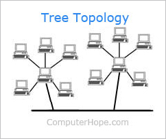
The advantages of Tree topologies are that expansion is easy and error detection and correction is also made simple. Another advantage to this topology is that when a node becomes damaged, it does not affect the remaining others.
However, there are disadvantages which are due to the basic structure of the Tree topology, that means the whole network heavily relies on the main bus cable, and if that breaks the entire network becomes somewhat 'crippled' and therefore rendered useless. Even though there is room for expansion regarding this topology, the more nodes that are added, the more complex maintenance becomes.
Mesh Topology
The mesh network topology is a form of LAN (Local Area Network) that has two variants; full mesh topology or partial mesh topology. Every node in the network is at least connected to two other nodes. The mesh network does not require an internet connection in order to be able to communicate amongst themselves.

Above I provided a diagram which should help learners understand how a mesh topology works, although the connections look like a star, the outer connections define it to make it into a mesh topology.
The advantages of the mesh topology are that data can be sent to and from different devices simultaneously, if a component fails there is usually always an alternative way to transfer data.
The disadvantages are that the cost is very high compared to the costs of the other topologies
SkyNet - SH
Thank you for reading through today's post, all about Network topologies that can make-up a network.
In a ring network each system and device is connected to two other devices either side. This forms a ring for the signals to travel around and each packet of data on the network travels in one direction, while each device receives each packet in turn until the destination device receives it.
In the above diagram, I have shown how the ring network topology works, each device/system has another device/system either side of it form a ring/circle.
The advantages of this type of network is that it can transfer data fairly quickly, even if there are a large number of devices connected because the data only flows in one direction. Another advantage is that there won't be any data collisions.
The disadvantages are that if one device/system has been shutdown or is inactive then the whole network will be down. Also if there is an issue on the network it can be hard to identify, therefore, making it hard to troubleshoot and resolve.
Star Topology
The star topology is a network that consists of central computer with connected nodes surrounding it, the greatest advantage to this topology is that if one node were to go down, then it would not affect the rest. However, if the main central computer system were to function incorrectly, then the whole network would be rendered 'down'.
The disadvantages of this network are that it can be expensive to set-up and install, due to the amount and cost of the required cables. Another thing that adds to the cost and therefore is considered a disadvantage is the amount of extra hardware needed, these can be hubs and switches.
Tree (Hierarchical) TopologyThe Tree topology is also known as the 'Star-bus topology' because the network set-up is similar to that of a Star and Bus topology. The Tree topology connects multiple Star topologies together, if the main cable which connected the two Star topologies failed, the multiple Star topologies would be unable to to communicate. However, the the systems on the individual topologies would still be able to function and communicate.
The advantages of Tree topologies are that expansion is easy and error detection and correction is also made simple. Another advantage to this topology is that when a node becomes damaged, it does not affect the remaining others.
However, there are disadvantages which are due to the basic structure of the Tree topology, that means the whole network heavily relies on the main bus cable, and if that breaks the entire network becomes somewhat 'crippled' and therefore rendered useless. Even though there is room for expansion regarding this topology, the more nodes that are added, the more complex maintenance becomes.
Mesh Topology
The mesh network topology is a form of LAN (Local Area Network) that has two variants; full mesh topology or partial mesh topology. Every node in the network is at least connected to two other nodes. The mesh network does not require an internet connection in order to be able to communicate amongst themselves.
Above I provided a diagram which should help learners understand how a mesh topology works, although the connections look like a star, the outer connections define it to make it into a mesh topology.
The advantages of the mesh topology are that data can be sent to and from different devices simultaneously, if a component fails there is usually always an alternative way to transfer data.
The disadvantages are that the cost is very high compared to the costs of the other topologies
SkyNet - SH
Thank you for reading through today's post, all about Network topologies that can make-up a network.
Thursday, 15 January 2015
Types of Network - SkyNet-SH
Hello and welcome to another post here at 'SkyNet-SH'. Today I will be explaining the different types of networks; LAN, WAN and Wireless. I will be giving a definition and then I will be supplying a clear diagram, showing basically how each network functions.
LAN (Local Area Network)
 |
| Figure 1. LAN Diagram (Thecustomizewindows.com, 2013) |
The Ethernet cable is the most common type of LAN for a PC, whereas AppleTalk is the alternative for Apple systems.
WAN (Wide Area Network)
 |
| Figure 2. WAN Diagram (Domainshane.com, 2012) |
WAN stands for Wide Area Network and can generally span over large geographical locations. This network consists of two or more LAN networks. Computer systems and devices are connected through public networks, such as the telephone line.
An example of a globally large scale WAN would be the Internet due to it covering almost all land-mass in the world.
TCP/IP is the protocol used for a WAN network in combination with devices and computer systems, such as; routers, switches, firewalls and modems.
An example of a globally large scale WAN would be the Internet due to it covering almost all land-mass in the world.
TCP/IP is the protocol used for a WAN network in combination with devices and computer systems, such as; routers, switches, firewalls and modems.
Wireless Network (WI-FI)
 |
| Figure 3. Wireless Diagram (A248.e.akamai.net, 2014) |
WI-FI is a rapid growing, popular wireless network that transmits data through radio-waves. Due to security reasons sometimes a password is needed in order to gain access to that network, therefore the Internet. Wireless networks are available in public places, such as; cafés and restaurants and also generally busy, populated areas, but are connected to at the user's risk, due to the insecure encryption allowing the possibility of an authorised, unknown person browsing through confidential files and information, while sitting at their own separate device. Although new devices come pre-built with wireless functionality, some old devices may not be able to connect to the wireless network, meaning that a wireless card may be needed.
FACT: The common misconception of WI-FI is that means 'Wireless Fidelity', however this is untrue and WI-FI is just a trademarked phrase that means 'IEEE 802.11x'. (Webopedia, 2014.)
FACT: The common misconception of WI-FI is that means 'Wireless Fidelity', however this is untrue and WI-FI is just a trademarked phrase that means 'IEEE 802.11x'. (Webopedia, 2014.)
Communication Device - SkyNet-SH
Hello and welcome to our first blog entry, here at 'SkyNet - SH'. Today we will be discussing the different types of communication devices and their limitations.
DTE - Data Terminal Equipment
Data Terminal Equipment is a device that controls the flow of data, going to or from a computer. The DTE can be a computer. A related factor is the DCE which is usually the modem, however, nowadays they are part of the same device. The DTE is also the interface that computer uses to exchange data with a modem or other serial devices. Common examples of Data Terminal Equipment are printers, routers and application servers.
Limitations of a DTE can be the RAM capacity, as if the device doesn't have enough RAM it can limit the speed of the flow of data. This is a limitation because without enough RAM, certain tasks cannot be fulfilled, therefore this will limit the functions and tasks that can be carried out via the DTE. Another limitation of DTE, would be that if there isn't enough onboard RAM, this would limit the amount of data that could be transferred over the network. Also due to the wired connectivity, if a cable/wire were to be damaged, this could potentially limit the functionality.
DCTE/DCE - Data Circuit Terminating Equipment or Data Communications Equipment
Data Communication Equipment is the RS-232C interface that a modem or other serial device uses in exchanging data with the computer. DCE's and DTE's are related and are now found to be part of the same device. Data Communications Equipment refers to computer hardware devices used to establish, maintain and terminate communication network sessions between a data source and its destination. The DCE is connected to the DTE and the Data Transmission Circuit (DTC) to convert transmission signals.
Limitations of a DCTE and DCE are that if there were viruses and other issues on the DCE (modem), then it would be rendered non-functional, also if a cable was damaged or plugged into the wrong port, then it could cause problems for the device and other connected devices. The reason as to why this is a limitation is that if the modem contracted a virus, then the user or network manager would be unable to transfer data in a safe environment. This is because the data would then be at a risk of potential unauthorised viewings or a breach of important and/or confidential data.
Another potential issue would be incompatible software and hardware and this may lead to users unable to access the internet or even get online. This is an issue because due to the forever growing lead of technology and protocols, older software and hardware is no longer needed or necessary. This means that companies have begun to use newer technologies, which means that support and compatibility of older software is concluded. Meaning when devices are used, only the latest software and hardware is recognised.
DTE - Data Terminal Equipment
Data Terminal Equipment is a device that controls the flow of data, going to or from a computer. The DTE can be a computer. A related factor is the DCE which is usually the modem, however, nowadays they are part of the same device. The DTE is also the interface that computer uses to exchange data with a modem or other serial devices. Common examples of Data Terminal Equipment are printers, routers and application servers.
Limitations of a DTE can be the RAM capacity, as if the device doesn't have enough RAM it can limit the speed of the flow of data. This is a limitation because without enough RAM, certain tasks cannot be fulfilled, therefore this will limit the functions and tasks that can be carried out via the DTE. Another limitation of DTE, would be that if there isn't enough onboard RAM, this would limit the amount of data that could be transferred over the network. Also due to the wired connectivity, if a cable/wire were to be damaged, this could potentially limit the functionality.
DCTE/DCE - Data Circuit Terminating Equipment or Data Communications Equipment
Data Communication Equipment is the RS-232C interface that a modem or other serial device uses in exchanging data with the computer. DCE's and DTE's are related and are now found to be part of the same device. Data Communications Equipment refers to computer hardware devices used to establish, maintain and terminate communication network sessions between a data source and its destination. The DCE is connected to the DTE and the Data Transmission Circuit (DTC) to convert transmission signals.
Another potential issue would be incompatible software and hardware and this may lead to users unable to access the internet or even get online. This is an issue because due to the forever growing lead of technology and protocols, older software and hardware is no longer needed or necessary. This means that companies have begun to use newer technologies, which means that support and compatibility of older software is concluded. Meaning when devices are used, only the latest software and hardware is recognised.
Laptops (Wired)
Wired laptops which are connected via an Ethernet cable are connected directly to the DCE (modem). The reason for having a wired connection would be that the connection would be faster, stronger and more efficient because usually on a wireless network at some times the internet speed may be slow, so the alternative is to use a wired connection. However, the limitations of having a wired connection would be the location of the modem and the laptop computer, for example, if the modem was encased in a box or cupboard, it would be difficult to access the ports depending on the length of the cable which would affect the portability. Other limitations would be unauthorised access to the laptop, in which the unauthorised user could infect the laptop or network with a virus.
Smartphones (Wireless)
The latest smartphones include wireless technologies, which allow for a wireless connection to the internet and network, an Ethernet cable which allows for a wired connection is not required and is also non-compatible. Even though the connection may be slower than wired connections, it is still fast enough for quick and easy browsing.
The limitations of wireless connections on smartphones are that the user must be in a fairly close range in proximity to the modem, because the further away from the modem, the slower and weaker the connection. Another limitation would be that during peak times (most internet traffic), the connection would be slow causing time consuming loading of webpages and websites, which also cause overload issues on servers. Another limitation regarding wireless smartphones would be due to wireless networks, which are known for having an unsteady connection. This means that the connection could potentially drop or fail at any given time, sometimes without notice. This could cause loss of work and/or network lag, which is the slowing of connection rates.
Functionality:
Switch
A switch divides the bandwidth and creates virtual circuits between each device and allows forwarding decisions to be made. It is mainly used to network multiple computers together. Switches and routers are similar, but switches don't provide the firewall and logging capabilities that routers do.
Router
A router routes data from a LAN (Local Area Network) to another separate network. Regarding security, a router only allows authorised systems to connect to the device. Most routers also keep log files about the local network activity.
A router routes data from a LAN (Local Area Network) to another separate network. Regarding security, a router only allows authorised systems to connect to the device. Most routers also keep log files about the local network activity.
Wireless Access Point
An access point is a device, such as a wireless router that allows devices that have a wireless capability. Most access points have built-in routers, while other access points need to be connected to a separate router. In both instances the wireless access point is wired to a network switch or broadband modem. Most access points allow the user to gain entry to a wireless network; the internet, but others can provide a gateway to Bluetooth devices, such as; headsets, smartphones and handheld games consoles.
Modem
Modem is a shortened form of 'Modulator-Demodulator' and is a communication device that can be either internal or external, regarding your computer. The functionality of a modem is that it allows one computer to connect to another and then send data to each other via a telephone line. The original dial-up modems are becoming obsolete because of their slow speeds and are being replaced by the much faster cable and DSL modems. An example of a DSL modem would be ADSL (Asymmetric Digital Subscriber Line).
Server
A server is a computer system that provides data for other computers and they can operate over a LAN network or a WAN network. There are many types of servers, including web servers, mail servers, and file servers. Each type of server requires its own specific piece of software in order to be able to cater for the jobs it needs to do. While software is specific to a server, hardware isn't.
The hardware needed to create and maintain a server are; a working host PC, a switch, cables, a router, back-up servers and possibly a printer (although its not necessary to have one.).
Thank you
Thank you all for taking your time to read through our very first blog post, I hope you have enjoyed and learnt something new from all the newly found information that I have inputted in this post. Looking over this post and through all the above information you may now begin to understand what aspects can make up a network.
Thank you all for taking your time to read through our very first blog post, I hope you have enjoyed and learnt something new from all the newly found information that I have inputted in this post. Looking over this post and through all the above information you may now begin to understand what aspects can make up a network.
Subscribe to:
Posts (Atom)